Warning !!! This is a draft, this is only a draft, please do not use these instructions to perform this procedure as there are mistakes and misspellings and a whole bunch of bad stuff that will surely blow up your engine. Please report any comments and corrections to DanO - Thanks.
DRAFT DRAFT DRAFT DRAFT
Fuel Injector Blueprinting
| Time, Total Time, Cost, First-Time Cost | 4hr, $150-200 |
| Number of Persons | 1 |
| Difficulty level | 7 |
| Tools | Micro torque wrench (to 7-13 lb-ft), 8,10,17mm sockets and various extensions, towels, rags, parts tray, 12mm socket (or 9mm hex wrench for after market strut bar), NSX Service Mat |
| Special Tools | Small flat-blade screwdriver, small dental-type hooking tool (optional) |
| Special Parts | Qty. 6, 16472-PH7-003 seal ring Qty. 6, 16473-PD6-000 cushion ring Qty. 6, 91301-PD6-003 o-ring Qty. 4, 90428-PD6-003 crush washer |
| Service Manual Pages | 11-92-93 |
For the sake of brevity, I'm going assume that the reader has at least some experience working on the NSX and has assembled a reasonable box of tools. Please don't take this procedure as gospel because it's not--use this as only one source of information.
The process of getting your injectors "blueprinted"
(cleaned and flow tested) is as follows:
Arrange for fuel injector cleaning and testing at a company
like RC Engineering www.rcneg.com
Order parts
Wait for parts to arrive
Receive and verify parts
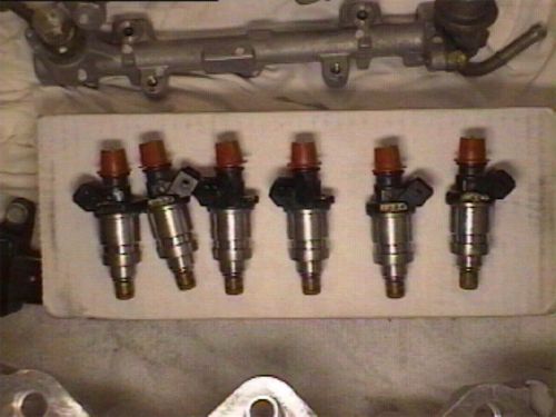
Remove the injectors
Ship the injectors
Wait a few days or weeks (car will be out
of commission during this period)
Install injectors
Drive!
Note: RC Engineering turned my injectors around in two days. Cost was $25 per injector. The injectors also came back with new cushion rings and o-rings.
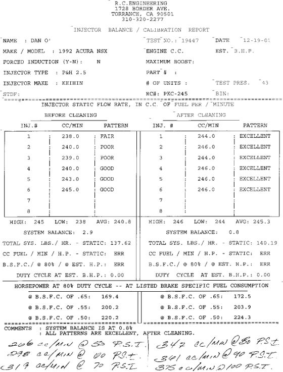
The report above came from RC Engineering and details the flow characteristics of the injectors taken on my '92 with about 40k miles. The left hand column show the flow in cubic cementers per minute (CC/MIN) for all 6 injectors before cleaning. As you can see some injectors flowed pretty well while others were not so good. The right hand column shows the flow after cleaning. The numbers below the top columns are all derived from the numbers in the table. Take a note of the Average flow rate and the System Balance numbers. As you can see, after cleaning the injectors flowed almost 5 cc/min more and the injectors are all flow within .8% (system balance) of each other. The B.S.F.C. (Brake Specific Fuel Consumption) numbers show total available engine horsepower at certain fuel pressure levels based on the new flow rates and a bunch of other factors and assumptions that are way out of the scope of this page and are not important for us to understand to do this procedure.
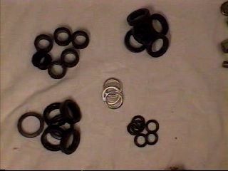
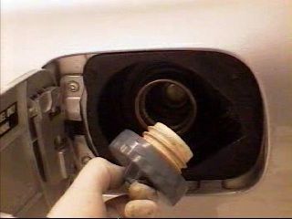
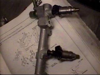
Parts: the above picture shows the various o-rings, seals and
crush washers needed to complete this project. I replaced the insulators
(upper right) but there's absolutely no reason to replace these.
Injector Removal
Warning! Please do not smoke or produce open flames while doing this procedure as you will be exposed to gasoline and gasoline fumes.
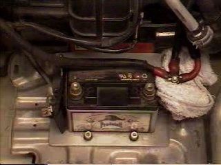
When working with gas, I like to completely disconnect the battery cables to avoid any possible sparks when working in the engine compartment.
Take a look at Service manual page 11-92. We'll be going right down the steps listed on this page.
1. Remove strut bar (service manual page 5-19).
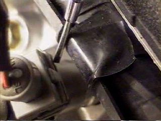
2. Relieve fuel pressure (service manual page 11-87). It's slightly more involved than the picture above <g>! Make sure you're in a well ventilated room when you're working on the gas system.
3. Remove the intake manifold covers (service manual 11-93). Requires a 8mm, 10mm socket and a 6mm(i think) hex wrench.
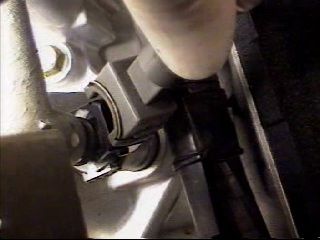
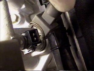
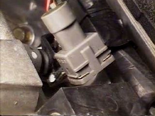
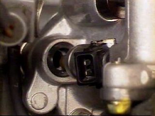
4. Disconnect the connectors from the injectors. OK, this is where it gets trying. There's got to be a better way but this is how I do it. Hopefully someone out there has a better way and I'll post it here. Take a small flat blade screwdriver and carefully push the wire spring retaining clip until it stays open against the side of the connector. Now do the same on the other side and at the same time, pull up on the connector. When the retaining spring is properly released, the connector will come off with very little effort. Do not pull too hard on the connector as this will accomplish nothing good. Once the connector is off put the spring back in its original position.
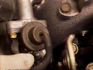
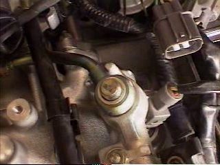
5. Disconnect the vacuum hose and fuel return hose from the pressure regulator. Twist the hoses as you remove them so that they don't crack. Put some rags around the regulator and hoses as some gas will most likely pour out.
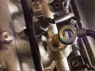
6. Disconnect the fuel hoses from the fuel rails, use 17mm socket. Note, you have to remove the fuel line that comes from the filter and ONE of the two rail-to-rail hoses. These connectors have a crush washer on either side so remove and discard these. Install new crush washers during installation. (service manual page 5-21). Be ready with rags to catch fuel.
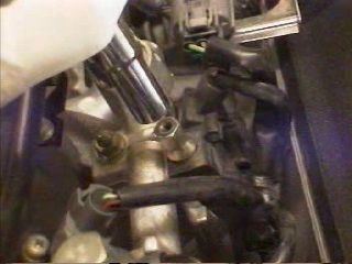
7. Remove the injector connector harness nuts and move the injector connector harness out of the way.
8. remove the (2 per rail) fuel pipe retainer nuts.
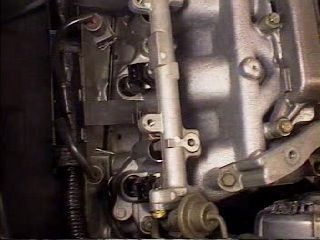
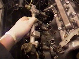
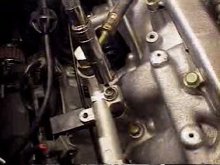
9. Carefully remove the fuel rails. They should pull right out. Be careful to not let the injectors fall out of the rail as they are just held in by friction.
Installation
Please see the service manual (page 11-93) for torque values.
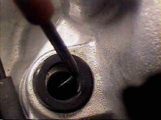
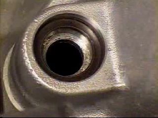
Use a small screwdriver or a dental hook tool and remove the old seal ring from the injector port on the intake manifold. There are two rings in the port, the top ring is soft rubber and should be replaced. The lower ring is metal and does not need to be replaced. Keep in mind that these holes go directly into your engine--take care not to drop anything in these holes!!!!
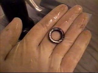
Use engine oil to coat the new seal rings and install them into the intake manifold.
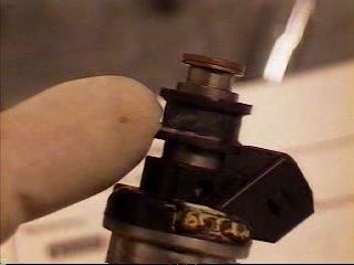
Install the cushion rings into the injectors
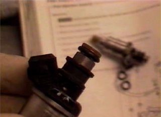
Coat the o-rings with engine oil and install on the injectors
Install the injectors into the fuel rail and align the connectors properly for manifold installation.
Install the fuel rails into the manifold.
Install the fuel rail nuts (9 lb-ft).
Install the connectors (reverse of removal).
Install the fuel hoses (torque to 16 lb-ft, 17mm socket). Place a new crush washer on either side of the banjo bolt--make sure the old crush washers are removed.
Install the connector harness
See step 20 on page 11-93: "Turn the ignition switch ON but do not operate the starter. After the fuel pump runs for approximately two seconds, the fuel pressure in the fuel line rises. Repeat this two or three time, then check whether there is any fuel leakage."
Install the manifold covers
Have a happy and safe test drive!